Documentation
Sample Gcode
Hardware Example
News Archive
Download
Buy Now
Payment, Shipping & Returns
Privacy Policy
Videos
Leadscrew Cover
PCB Cutout
Pinion Gear
G64 Path Blending
Fusion 360 Clamps
Fusion 360 Threads
Sherline
Shapeoko 2
Gecko G540
Sherline 3D Printer
Sherline Leadscrew Cover Mounting Plate
Sample Gcode for Sherline Leadscrew Cover Mounting Plate
Here is a good example using PyMini software with the rt-stepper hardware. This gcode file is used to create the following leadscrew cover mounting plate. Fusion 360 3D CAD/CAM was used to generate this gcode file. You can view the tool path offline with PyMini using the Verify button. The gcode file is a simple text file you can look at with any standard text editor. If you want I have included the .dxf file so you can create a new gcode file with your own CAD/CAM software, just be sure select LinuxCNC(EMC2) configuration at Post Process time.
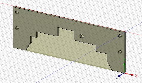
leadscrew_cover_plate.nc leadscrew_cover_plate.dxf
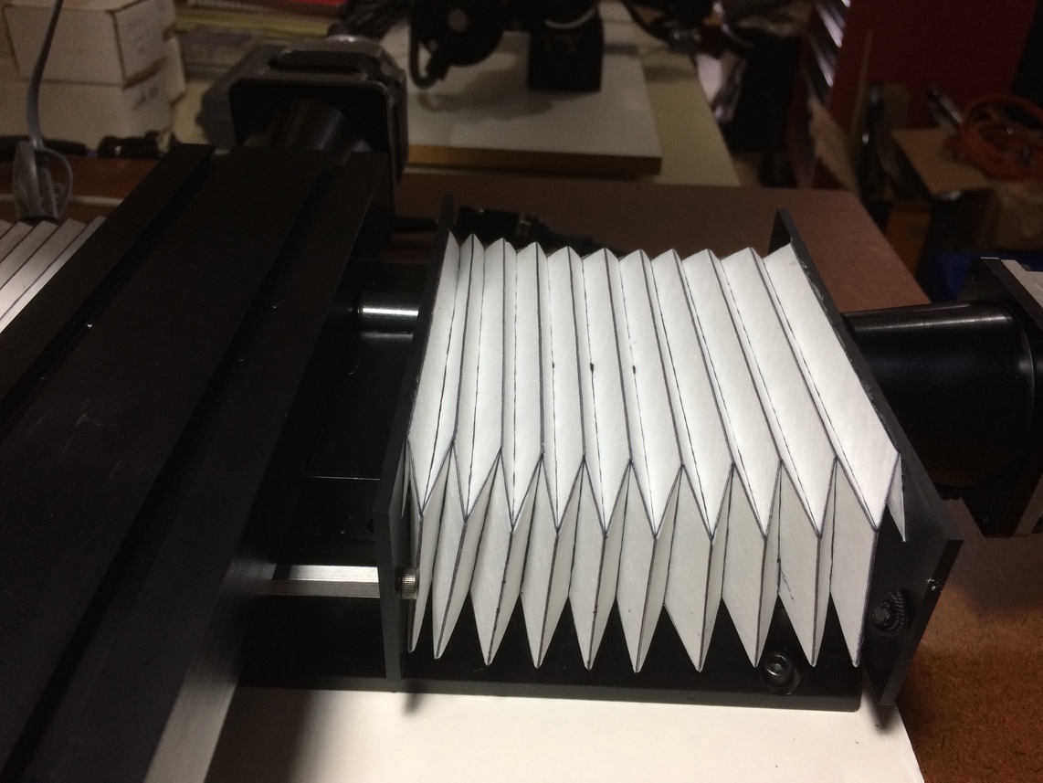
The mounting plate shown here uses a origami type bellow cover.
The original idea came from the leadscrew project presented at www.ixen-cnc.com, but the site is no longer valid.
I have posted the following URLs so you can still make your own origami bellows cover.
Here is the origami bellows cover video that shows you how to make the bellows.
Here is the bellows cutout .pdf file referenced in the video.
I like this design because it fits well on my Sherline mill. The cover is very compact and does not waste Y axis movement like some other designs.
Even with the longer Y axis on my Sherline 14 inch base, the cover will expand and compress without loosing shape.


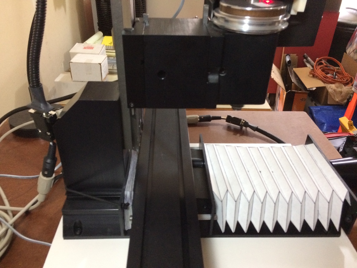
All four mounting plates are identical. The two inside plates mount to the saddle with a single screw and no modifications to the mill. The two end plates mount to the mill with 1/8 inch bungee cord and cord locks. You can use plastic or aluminum material for the plates. I used .125 inch black styrene for my plates.
For bellows material I used white "sew-in interfacing" material which is available at any fabric store. Interfacing is made of man-made fibers bonded together to form a paper-like sheet. The material I bought was about .012 inch thick, product name was "pellon 884 cut-a-way stablizer". I tried other bellows material (ie: plastic sheets, fusible interfacing), but this material was easier to work with and still maintained it's shape after folding.
Here are some caveats for building the bellows.
- Download the bellows cutout .pdf file.
- Cutout two 12x8 inch sheets of interfacing.
- If necessary iron the sheets to make sure they are flat.
- Print the .pdf file on each sheet as actual A4 paper size. I used a standard HP LaserJet 1320, bottom paper input bin.
- Using the video as a reference take each sheet and score each fold line with a ball point pen on a soft surface. The scoring will make the folding much easier and more accurate.
- Cutout the shape of the bellows template using a x-acto knife.
- As shown in the video make the appropriate folds on each sheet.
Once you have the two bellow covers built attach each cover to two end plates. I used DAP clear silicone rubber sealant for this procedure with good results
Here is a view of the front and back plates.
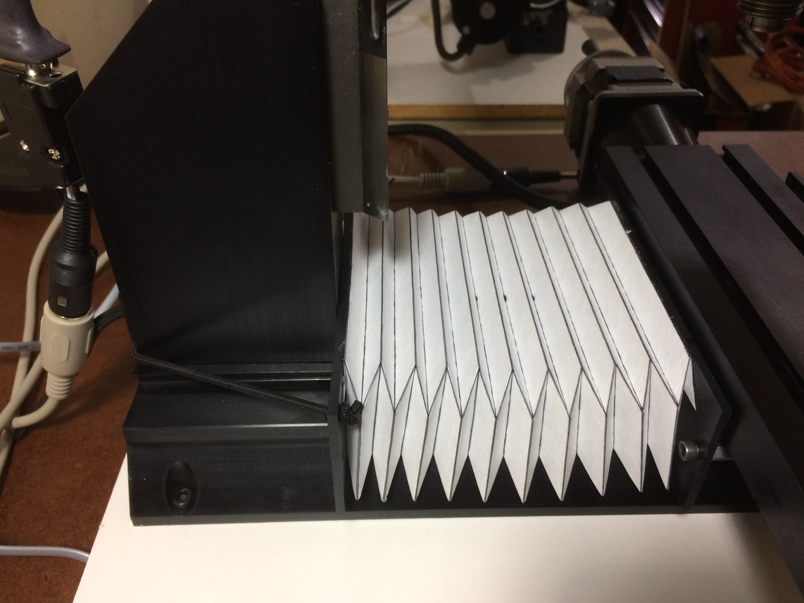
Here is a view of how the front inside plate mounts to the saddle. Use the 10-32 socket head screw that holds the table lock assembly. Don't over tighten this screw or you will lock your table.

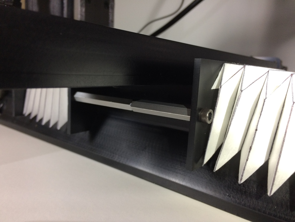
The inside plates are connected together with two 8-32, 3.5 inch hex standoffs. One standoff for each side of the saddle. To make one 3.5 inch standoff I used two smaller standoffs together. A 1.5 inch and 2 inch (McMaster-Carr #91780-A202 and #91780-A204).
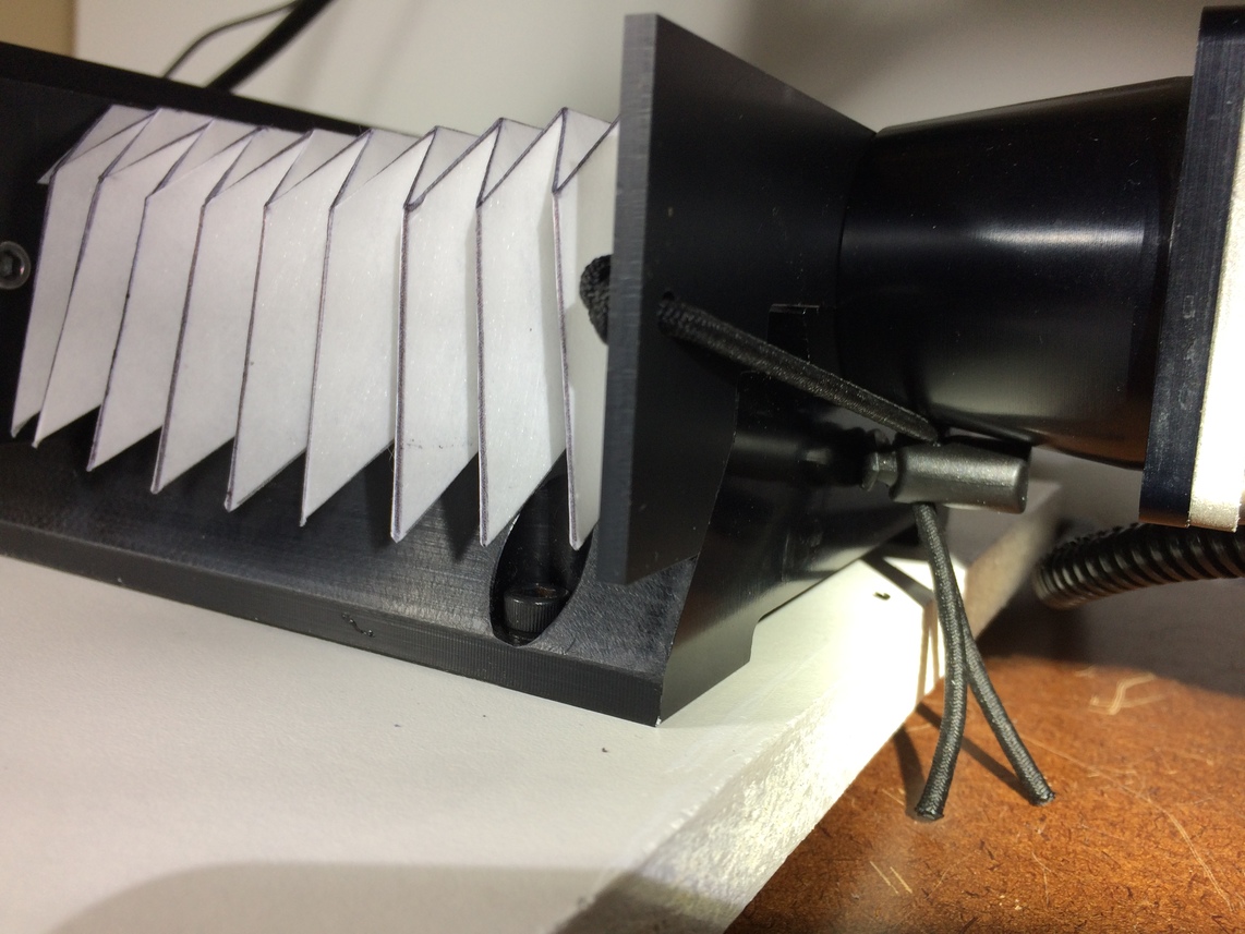
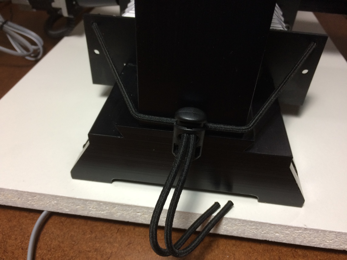
Here is a good view of the bungee cords used to mount the front plate to the mill. I used a cord lock with the bungee cords so I could easily attach/remove the plate later. The back plate was mounted in a similar manner.