Documentation
Sample Gcode
Hardware Example
News Archive
Download
Buy Now
Payment, Shipping & Returns
Privacy Policy
Videos
Leadscrew Cover
PCB Cutout
Pinion Gear
G64 Path Blending
Fusion 360 Clamps
Fusion 360 Threads
Sherline
Shapeoko 2
Gecko G540
Sherline 3D Printer
Spindle Synchronized Threading
Sample Gcode for Spindle Synchronized Threading
Here we demonstrate how to do single point threading using the G33 command. Both G33 and G76 can be used for threading, but here we will only use the G33 command because that is what Fusion 360 CAD/CAM supports. For gcode command syntax see the "Gcode Overview" section at www.linuxcnc.org.Spindle synchronization is provided by INPUT0 index pulse. See the Spindle Speed section for connecting a index pulse to the rt-stepper dongle. When using the G33 command PyMini will automatically read the spindle speed in order to calculate the distance for each revolution of the spindle. Note, if no index pulse is detected by PyMini no synchronization is performed.
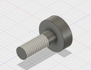
Here is a 10-32 screw I designed using Fusion 360. Two gcode files where created, one to cut the shape of the screw and another to cut the threads.
screw_shape_10-32.nc screw_thread_10-32.nc |
|---|
- When creating the CAM ouput use the "pymini turning.cps" post processor file. The default "linuxcnc turning.cps" post processor file did not support synchronized threading. The "pymini turning.cps" file is a modified version of the "linuxcnc turning.cps" file.
- CAM output uses G7 diameter mode for X axis. This means a "G0 X1" command would move X position to 0.5.
- Make sure the G33 commands uses the correct thread pitch value for "K". This is a CAM Setup value.
- Make sure all other G1 commands use the correct feedrate (ie: 20 ipm for Sherline). This is a CAM Setup value.
- On the lathe set the Z origin. Touch off the Z by making a surface cut at the tail end of the part. Or use a piece of paper to set the Z.
- On the lathe set the X origin. Fusion 360 CAM puts the XZ origin on the center axis of the part (Note, G76 assumes the X origin is at the outer radius of the part). Touch off X by making a small surface cut then measure the diameter (D). Use the D value later in step 4.
- With Z set in the above step, click the "All Zero" button in PyMini.
- Now set the X position to D/2 using the PyMini M191 command. For example if D/2 = 0.225 use the this MDI command "M191 P0 Q0.225".
- On your lathe set the spindle speed. For my Sherline lathe I set the spindle speed to 100 RPM and the spindle pulley belt position set to high torque. The Sherline spindle has higher torque at low RPMs.
- Now you can run the gcode file.
- After threading is complete use the "M193" command to see the Minimum/Maximum RPM measured while executing the G33 commands. The important measurement here is the Minimum RPM value. If your spindle speed slows down too far during threading you will not get accurate threads cut.
Here is a picture of 10-32 screw after threading with Sherline 4000 CNC lathe. A 10-32 nut was attached to check for accuracy. This screw was successfully made out of aluminum.
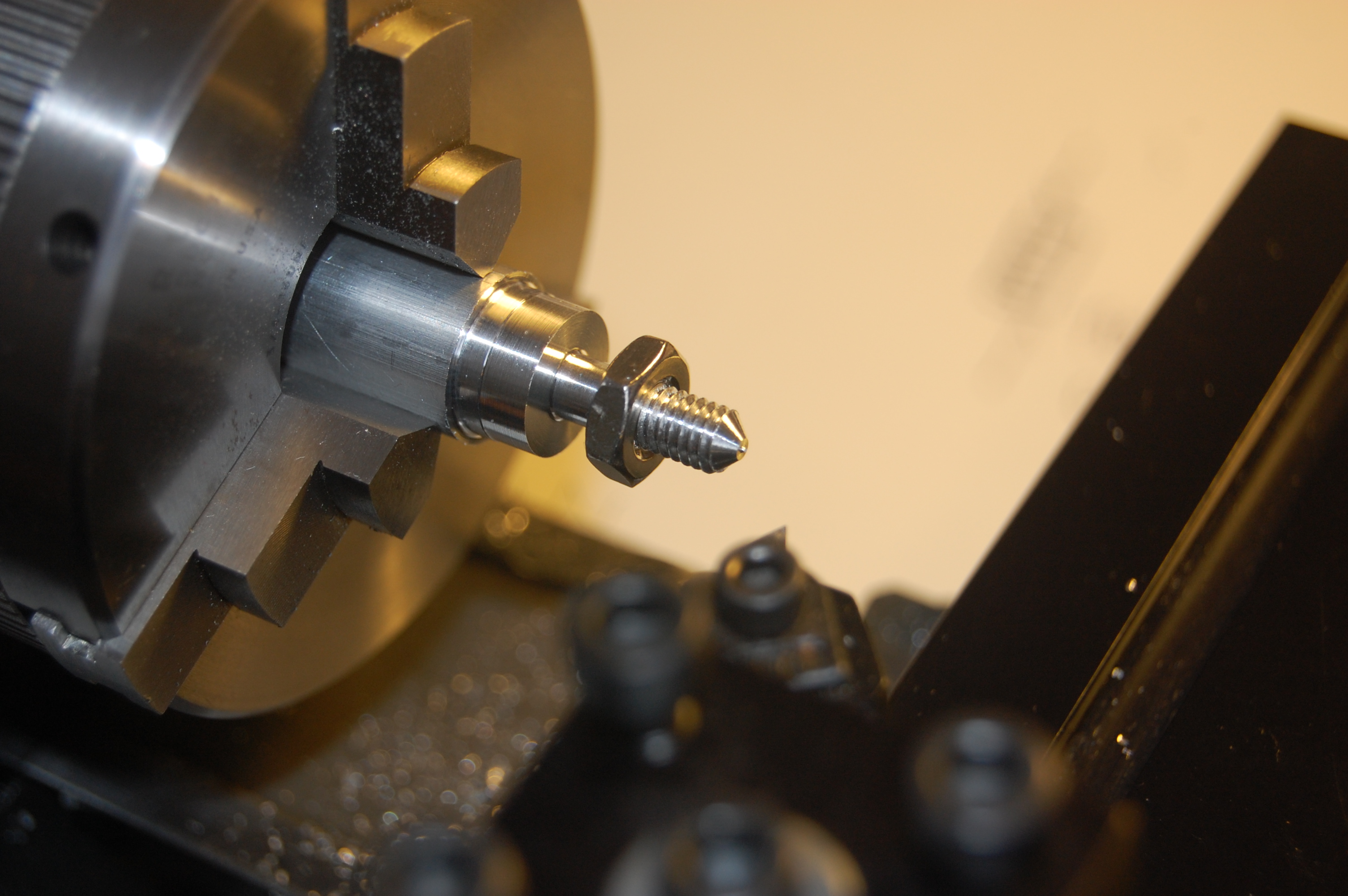
M193 runtime stats:
 current rpm=98.93 rpm_avg=99.02
 spindle synchronized rpm_max=100.56 rpm_min=92.18
Depending on part material, thread diameter and spindle torque your results may vary.
